Resonant Capacitors: Your Key to Building Stable and Reliable Wireless EV Charging Technology

Blog post from Knowles Precision Devices. Starvoy represents Knowles across Canada, for further information please reach out to our sales team.

As electric vehicle (EV) adoption for both consumer and commercial purposes rapidly grows, so does the need for a more widespread, and faster, charging infrastructure. While we’ve seen vast improvements in charging technology in the last few years, as additional regulations on combustion vehicles are implemented and reliance on EVs increases, further EV charging innovations are needed. Currently, wireless charging is the newest EV charging technology evolving.

Read More

Instrumentation News – Coherent’s WaveShaper, WaveAnalyzer & WaveMaker

Below are some updates from Coherent, a leading provider of test and measurement instruments for optical communications technology, including solutions designed for the Super-C Band.

For further information, feel free to reach out to the Starvoy team to arrange a meeting at our Kanata Test & Measurement Lab, one of our other offices, or whilst we are visiting OFC (6th – 9th March 2023, San Diego).

Introducing WaveShaper® 1000B and 4000B covering the Super C-Band

Coherent introduces the WaveShaper 1000B and 4000B covering the Super C-Band. The 1000B has a 1×1 and the 4000B a 1×4 port configuration. Both units support arbitrary spectral filter shapes of attenuation and phase across the entire operating range from 1523.142 nm to 1573.301 nm. A minimum filter bandwidth of 10 GHz (FWHM) is available. When selecting the “High Resolution” mode – which applies a double pass configuration inside the instrument – the minimum bandwidth reduces to 8 GHz.

Read More

Qorvo: How to Get Smaller, Smarter, More Reliable Power Management

In this industry, it can be easy to take power for granted. Easy, of course, until you don’t have it. Managing that vital resource is critical for systems to operate properly, and in a world that demands smaller, faster and smarter devices, it can be a real challenge. But what if a built-in power management device helped tackle that job? Qorvo’s Configurable Intelligent Power Solutions (ActiveCiPS™) devices help control, monitor and optimize power distribution and conversion in different systems with built-in intelligence and configurability.

In complex systems, or when a designer needs a more advanced or innovative power solution, it can be too expensive to use discrete components. Power Management Integrated Circuits (PMICs) integrate multiple voltage regulators and control circuits into a single chip. Today’s PMICs are flexible, allowing users to update default settings like output voltages, sequencing, fault thresholds and other parameters. As a result, PMICs are used in many small devices such as wearables, hearables and IoT (Internet of Things) devices – all thanks to their small size, high efficiency and low power consumption. These tiny, high-performance PMICs maximize system efficiency and performance while providing design flexibility and lowering the bill-of-materials cost.

Read More

Qorvo® Biotechnologies Awarded $4.1 Million National Institutes of Health Contract for SARS-CoV-2/ Flu Combo and Antigen Pooling

GREENSBORO, NC – February 7, 2022 – Qorvo® (Nasdaq:QRVO), a leading provider of innovative RF solutions that connect the world, announced it has been awarded a $4.1 million follow-on contract with the National Institutes of Health (NIH) through the Rapid Acceleration of Diagnostics (RADxSM) initiative. The contract, awarded to Qorvo Biotechnologies, a wholly owned subsidiary of Qorvo, will help advance the clinical trials and market launch of both a SARS-CoV-2/ Flu Combo Assay and SARS-CoV-2 Antigen Pooling on the Qorvo Omnia™ diagnostic test platform.

The SARS-CoV-2/Flu Combo Assay will simultaneously detect and differentiate between SARS-CoV-2, Flu A and Flu B in an all-in-one test using a single swab sample in approximately 20 minutes. The antigen pooling application will allow up to six samples to be processed together and tested at the same time. Antigen pooling enables significant time and cost savings for screening groups of people who aren’t experiencing SARS-CoV-2 symptoms. Qorvo continues to develop advanced testing formats for SARS-CoV-2 detection in response to the pandemic while focusing on test performance, workflow efficiencies and cost control for end users. Combined with a previous NIH contract award of $24.4 million, this award positions Qorvo to accelerate the production and market launch of multiple COVID testing solutions using a single platform.

Philip Chesley, president of Qorvo Biotechnologies, said, “Today’s COVID testing market is demanding high quality testing infrastructure at the point of care (POC), with automated workflow, menu expansion and scalability to serve future needs of the pandemic. This contract award and continued RADx support enable Qorvo to more effectively address the expanding requirements of diverse end use settings.”

Tiffani Bailey Lash, Ph.D., Co-Program Lead for the RADx Tech program, said, “Qorvo’s antigen test has a lot of potential with near-PCR-level accuracy for use at POC settings.”

The Qorvo Omnia platform represents an innovative diagnostic technique by using high frequency Bulk Acoustic Wave (BAW) sensors to achieve rapid SARS-CoV-2 (COVID-19) antigen test results. BAW sensor technology enables low limit of detection (LOD) levels similar to molecular testing capability.

For more information, visit www.qorvobiotech.com.

This project has been funded in whole or in part with Federal funds from the National Institute of Biomedical Imaging and Bioengineering, National Institutes of Health, Department of Health and Human Services, under Contract No 75N92021C00008.

The Qorvo Omnia SARS-CoV-2 Antigen Test was granted emergency use authorization (EUA) from the U.S. Food and Drug Administration (FDA) in April 2021. The test is authorized for the qualitative detection of nucleocapsid viral antigens from SARS-CoV-2 in nasal swab specimens from individuals who are suspected of having COVID-19 by their healthcare provider within the first 6 days of symptom onset. The Qorvo Omnia SARS-CoV-2 Antigen Test has not been FDA cleared or approved. It has been authorized by the FDA under an Emergency Use Authorization and testing is limited to laboratories certified under the Clinical Laboratory Improvement Amendments of 1988 (CLIA), 42 U.S.C. §263a, to perform moderate or high complexity tests. This test has been authorized only for the detection of proteins from SARS-CoV-2, not for any other viruses or pathogens. These tests are only authorized for the duration of the declaration that circumstances exist justifying the authorization of emergency use of in vitro diagnostic tests for detection and/or diagnosis of COVID-19 under Section 564(b)(1) of the Act, 21 U.S.C. § 360bbb-3(b)(1), unless the authorization is terminated or revoked sooner.

About Qorvo Biotechnologies
Qorvo Biotechnologies, LLC is a wholly owned subsidiary of Qorvo, Inc. focused on the development of point-of-care (POC) diagnostics solutions leveraging Qorvo’s innovative BAW sensor technology.

About Qorvo
Qorvo (Nasdaq: QRVO) makes a better world possible by providing innovative Radio Frequency (RF) solutions at the center of connectivity. We combine product and technology leadership, systems-level expertise and global manufacturing scale to quickly solve our customers’ most complex technical challenges. Qorvo serves diverse high-growth segments of large global markets, including advanced wireless devices, wired and wireless networks and defense radar and communications. We also leverage unique competitive strengths to advance 5G networks, cloud computing, the Internet of Things, and other emerging applications that expand the global framework interconnecting people, places and things. Visit www.qorvo.com to learn how Qorvo connects the world.

Qorvo is a registered trademark of Qorvo, Inc. in the U.S. and in other countries. All other trademarks are the property of their respective owners.

Media Contact:
Brent Dietz
Qorvo Director of Corporate Communications
+1 336-678-7935
[email protected]

This press release includes “forward-looking statements” within the meaning of the safe harbor provisions of the Private Securities Litigation Reform Act of 1995. These forward-looking statements include, but are not limited to, statements about our plans, objectives, representations and contentions, and are not historical facts and typically are identified by use of terms such as “may,” “will,” “should,” “could,” “expect,” “plan,” “anticipate,” “believe,” “estimate,” “predict,” “potential,” “continue” and similar words, although some forward-looking statements are expressed differently. You should be aware that the forward-looking statements included herein represent management’s current judgment and expectations, but our actual results, events and performance could differ materially from those expressed or implied by forward-looking statements. We do not intend to update any of these forward-looking statements or publicly announce the results of any revisions to these forward-looking statements, other than as is required under U.S. federal securities laws. Our business is subject to numerous risks and uncertainties, including those relating to fluctuations in our operating results; our substantial dependence on developing new products and achieving design wins; our dependence on several large customers for a substantial portion of our revenue; the COVID-19 pandemic materially and adversely affecting our financial condition and results of operations; a loss of revenue if defense and aerospace contracts are canceled or delayed; our dependence on third parties; risks related to sales through distributors; risks associated with the operation of our manufacturing facilities; business disruptions; poor manufacturing yields; increased inventory risks and costs due to timing of customer forecasts; our inability to effectively manage or maintain evolving relationships with platform providers; our ability to continue to innovate in a very competitive industry; underutilization of manufacturing facilities as a result of industry overcapacity; unfavorable changes in interest rates, pricing of certain precious metals, utility rates and foreign currency exchange rates; our acquisitions and other strategic investments failing to achieve financial or strategic objectives; our ability to attract, retain and motivate key employees; warranty claims, product recalls and product liability; changes in our effective tax rate; changes in the favorable tax status of certain of our subsidiaries; enactment of international or domestic tax legislation, or changes in regulatory guidance; risks associated with environmental, health and safety regulations and climate change; risks from international sales and operations; economic regulation in China; changes in government trade policies, including imposition of tariffs and export restrictions; we may not be able to generate sufficient cash to service all of our debt; restrictions imposed by the agreements governing our debt; our reliance on our intellectual property portfolio; claims of infringement of third-party intellectual property rights; security breaches and other similar disruptions compromising our information; theft, loss or misuse of personal data by or about our employees, customers or third parties; provisions in our governing documents and Delaware law may discourage takeovers and business combinations that our stockholders might consider to be in their best interests; and volatility in the price of our common stock. These and other risks and uncertainties, which are described in more detail in Qorvo’s most recent Annual Report on Form 10-K and in other reports and statements filed with the Securities and Exchange Commission, could cause actual results and developments to be materially different from those expressed or implied by any of these forward-looking statements.

Boosting Bandwidth to Future-Proof CATV Solutions

Original blog post from: https://www.qorvo.com/design-hub/blog/boosting-bandwidth-to-future-proof-catv-solutions

Future entertainment systems and work-at-home environments are rapidly moving toward greater two-way interaction, which calls for enhanced downstream bandwidth and upstream capabilities. To stay competitive in the evolving CATV business, innovative technologies are needed to keep up with demands. One component that can play a vital role in this evolution is the CATV amplifier based on gallium nitride (GaN) technology. This post provides insight into how to do just that. The following is an excerpt from a Qorvo white paper, How to Increase Downstream Bandwidth and Upstream Capabilities in CATV Amplifiers with Greater Efficiency.

Meeting Higher Uplink Bandwidth Demands

Typical allocations for upstream traffic on Hybrid Fiber Coax (HFC) networks in the US range from 5 MHz to 42 MHz. User activities and new use cases are driving the need for increased capacity. In response, some multiple system operators (MSOs) are setting mid-splits or high-splits within the available bandwidth to accommodate these demands, reducing downstream bandwidth and possibly curtailing content or services.

MSOs facing this challenge are exploring the options available through DOCSIS 3.1 or DOCSIS 4.0 specifications. Upstream capacity within DOCSIS 3.1 can be extended up to 204MHz. While DOCSIS 4.0 allows the upstream to go up to 684MHz in both full duplex (FDX) and extended spectrum DOCSIS (ESD). Figure 1 shows how full duplex (FDX) let upstream and downstream traffic share the 684 MHz frequency range.

Take a Deeper Dive

Download the White Paper


Figure 1. DOCSIS 4.0 FDX spectrum for upstream (US) and downstream (DS).

Maintaining Linearity

The trend toward extended CATV bandwidth has led engineers and system architects to explore new technologies as networks are upgraded, requiring a newer generation of passive and active products. To meet demands for the increased bandwidth and data rates, CATV amplifiers must maintain a higher linear output power.

Gallium Nitride (GaN) devices can deliver more than the necessary efficiency and performance to satisfy DOCSIS requirements for CATV amplifiers. Consistent linearity is a primary requirement for reliable data transmission and signal integrity across HFC networks. The nonlinear behavior of active power devices can degrade the signal quality, leading to bit errors on digital channels and sometimes complete failure when trying to demodulate the signal.

Linearity of a gain block or amplifier depends primarily on these factors:

  • Semiconductor technology
  • Circuit design
  • Power consumption
  • Thermal design


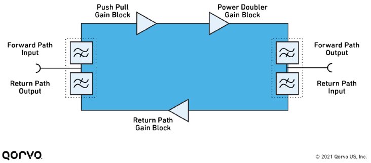
A high degree of linearity and efficiency are paramount when designing an HFC amplifier, and this is where GaN-based components have a clear advantage. Figure 2 shows the fundamental components of a CATV amplifier. In terms of linear output, the downstream performance of an HFC amplifier or node largely relies on the output stage gain block (also called the power doubler).

What is DOCSIS?

Data Over Cable Service Interface Specification (DOCSIS) is an international telecommunications standard that permits the addition of high-bandwidth data transfer to an existing cable television (CATV) system. It is used by many cable television operators to provide Internet access over their existing hybrid fiber-coaxial (HFC) infrastructure. The version numbers are sometimes prefixed with simply “D” instead of “DOCSIS” (e.g., D3 for DOCSIS 3).


Figure 2. Block diagram of a CATV amplifier.

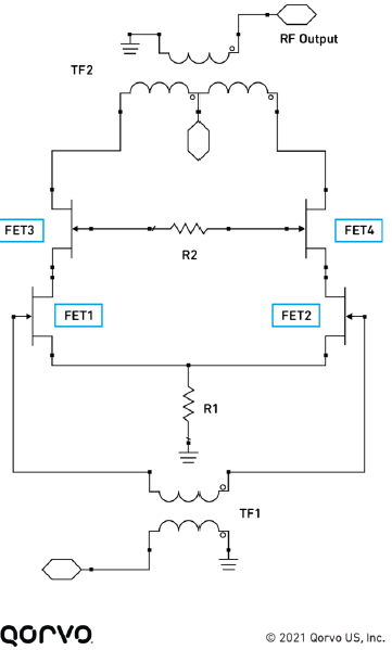
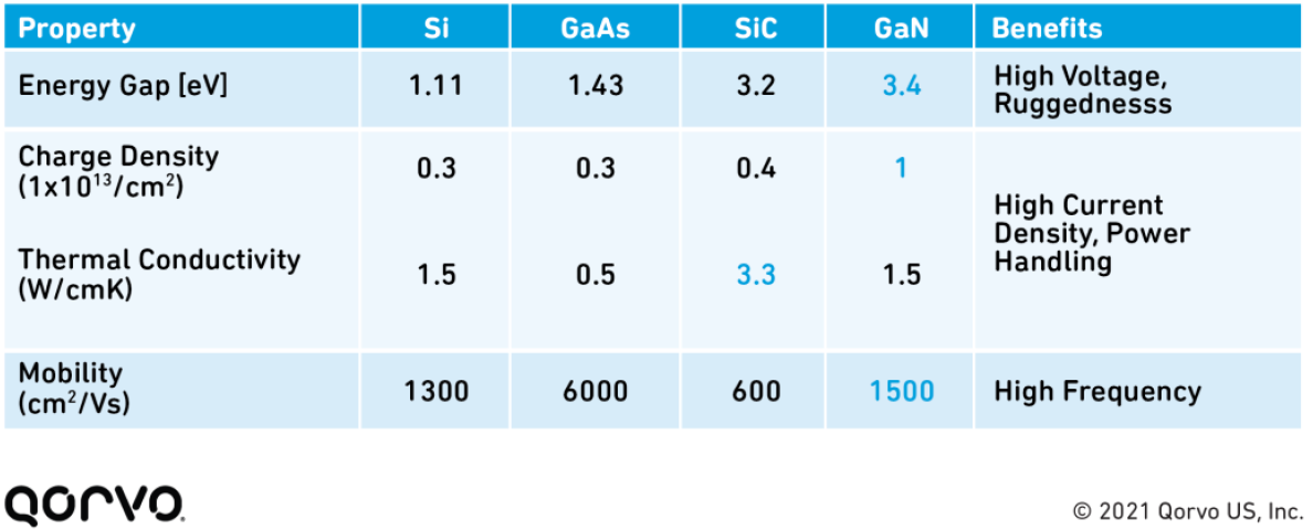
GaN represents an enabling technology for power amplifier designs that can accommodate the demands of the DOCSIS 3.1 and DOCSIS 4.0 standards. Figure 3 illustrates a design stage that originally implemented the gain block architecture using field-effect transistors (FETs) based on GaAs technology. Replacing FET3 and FET4 with GaN-based components results in a substantial performance improvement because of the characteristics of these devices, including operation at high frequencies, high-voltage ruggedness, high current density, and power handling. GaN supports up to 10 W/mm compared to 1 W/mm for GaAs.


Figure 3. Gain block architecture improved through the use of GaN-based FETs.

Comparing the relative characteristics of material technologies used in CATV gain-block architecture, Figure 4 shows the advantages of GaN technology, enabling MSOs to boost linear output while maintaining existing amplifier spacing. This can minimize upgrade costs and make it possible to implement fiber deep solutions, locating fiber closer to the customer to enhance service and at the same time reducing or eliminating amplifiers.


Figure 4. Characteristics of GaN-based components compared to other options.

Qorvo Expertise in CATV Gain Blocks

Two Qorvo products are outstanding design choices in this sector:

  • QPA3260 power doubler hybrid – Delivers the highest linear output up to 1.2 GHz
  • QPA3315 power doubler hybrid – Supports DOCSIS 4.0 implementations in designs requiring up to 1.8 GHz capabilities


With the need for greater downstream bandwidth and increased upstream capacities spurred by DOCSIS 3.1 and DOCSIS4.0 standards, Qorvo can help MSOs respond to the challenge with GaN-based gain blocks for CATV signal amplification. CATV equipment manufacturers can rely on proven solutions that deliver better data transport using durable and reliable components.


Have another topic that you would like Qorvo experts to cover? Email your suggestions to the Qorvo Blog team and it could be featured in an upcoming post. Please include your contact information in the body of the email.

Explore the Qorvo Blog

About the Author

Rainer Hillermeier
General Manager, Design and Operations – Qorvo Germany

Rainer manages Qorvo’s Design and Manufacturing Site in Nuremberg, Germany. With more than two decades of high power CATV gain blocks design experience, Rainer oversaw the development and release of the first 1 GHz, 1.2 GHz and now 1.8 GHz gain blocks. He also pioneered the introduction of GaN semiconductor technology in hybrid fiber-coax infrastructure products.

Lights, Camera, Action! UWB is the Star Supporter in Le Premier Royaume

With all the potential use cases for ultra-wideband (UWB) technology, it’s not surprising that it’s often found in the most unexpected places. Case-in-point: the Puy du Fou theme park in France. A recent article in blooloop outlines how UWB rescued its show “Le Premier Royaume” (“The First Kingdom”), a multi-sensory walkthrough experience set in fifth-century France, in which guests journey through the history and legend of the Frankish King Clovis.

According to the article, “During the experience, five hundred theater goers move through the sets, as eight actors execute perfectly timed entrances and exits. This is supported by lights, sound, and special effects.” The show cycles for seven hours a day, using 14 different sets throughout roughly 24,000 square feet on two levels. The challenge for the show producers was to keep pace with the visitors moving through the spaces and timing the activation of the show’s effects.

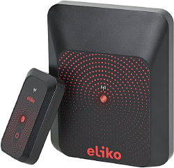
That’s where UWB came in. Puy du Fou turned to Eliko’s UWB RTLS system, which integrates Qorvo’s UWB devices and can track hundreds of objects in real-time.

Here we explore why UWB technology is conducive for precision-dependent use cases.

figure 1

Eliko’s UWB RTLS system integrates Qorvo’s UWB devices and can track hundreds of objects in real-time.

UWB: Solving the ‘Where’

In show business, timing is everything. Especially for the Le Premier Royaume performance. What’s also critical for the show’s success is the ‘where.’ The timing of the lighting, special effects, actors are all based on where the audience is located in relation to its location within the theater. We have many technologies—BLE, Wi-Fi, RFID, etc.—and apps built into so many of our devices that accurately track the ‘when’ and inform us of ‘what.’ But they’re not designed to track the ‘where,’ the precise location in real-time—second by second. However, this is exactly what ultra-wideband does.

With UWB, the show’s production could synch all the devices so the apps always know precisely where things are—down to the centimeter and the second. Being a low-power, ultra-wide bandwidth radio technology, UWB offers characteristics that make it ideal for use cases such as Puy du Fou’s—the most important in this case are precision ranging, precise location, and fast data communication.

Why UWB?

To better understand why UWB, in particular, is the most conducive for applications like Puy du Fou’s – a challenging environment for RF technologies – let’s take a look at how it compares to other technologies like BLE and Wi-Fi. This table shows that UWB has all the ingredients to overcome the show’s challenges.

figure 1

A scene from “Le Premier Royaume” (“The First Kingdom”), a multi-sensory walkthrough experience set in fifth-century France.

UWB Bluetooth® Low Energy Wi-Fi
Accuracy Centimeter 1-5 meters 5-15 meters
Reliability Strong immunity to multi-path and interference Very sensitive to multi-path, obstruction and interference Very sensitive to multi-path, obstruction and interference
Range/coverage Typ. 70m
Max 250m
Typ. 15m
Max 100m
Typ. 50m
Max 150m
Data Communications Up to 27 Mbps Up to 2 Mbps Up to 1 Gbps

What sets UWB apart the most from the other technologies is its accuracy. Like other location technologies, UWB doesn’t rely on satellites for communication. Instead, devices containing UWB technology (like antennas on the show’s actors, lighting, cameras, etc.) communicate directly with each other to determine location and distance. What’s different about UWB from the others is this accuracy is achieved by measuring the time that it takes signal pulses to travel between devices, which can be calculated based on the time-of-flight of each transmitted pulse.

The accuracy of this method depends on the signal’s bandwidth; very wide signals are needed to achieve high accuracy. UWB signals use roughly 500 MHz of bandwidth—many times wider than other technologies sometimes used for location sensing. That enables UWB to achieve centimeter precision, which is critical for many applications.

UWB technology also works in non-line-of-sight conditions where the use of cameras to track location is not possible. This means that the signal is capable of going through obstructions like the sets while maintaining a very high location accuracy. In addition, as it operates at frequencies between 6 and 8GHz, it has no interference issues with other radio waves.

For more in-depth information about how UWB technology works, read the whitepaper, Getting Back to Basics with Ultra-Wideband (UWB).

Check Out Other UWB Use Cases

UWB is an old radio technology enabling new opportunities for rich real-time applications. Companies and application developers are already enabling new UWB-based services that benefit both businesses and individuals. But they are only scratching the surface. There are many use cases where UWB can create an experience and enrich our personal lives. For more ideas on use cases, watch this video. You can also read about how UWB is used at the Museum of the Bible to enhance the visitor experience, as well as how Volkswagen is optimizing its production by integrating UWB into its operations.

The Bluetooth® word mark and logos are registered trademarks owned by Bluetooth SIG, Inc. and any use of such marks by Qorvo US, Inc. is under license. Other trademarks and trade names are those of their respective owners.

What Designers Need to Know to Achieve Wi-Fi Tri-Band Gigabit Speeds and High Throughput

Original post from: https://www.qorvo.com/design-hub/blog/what-designers-need-to-know-to-achieve-wi-fi-tri-band-gigabit-speeds-and-high-throughput

Engineers are always looking for the simplest solution to complex system design challenges. Look no further for answers in the U-NII 1-8, 5 and 6 GHz realm. Here we review how state-of-the-art bandBoost™ filters help increase system design capacity and throughput, offering engineers an easy, flexible solution to their complex designs, while at the same time helping to meet those tough final product compliance requirements.

A Summary of Where We are Today in Wi-Fi

Wi-Fi usage has grown exponentially over the years. Most recently, it has skyrocketed upward to unimaginable levels — driven by the pandemic of 2020 due to work from home, school requirements, gaming advancements, and, of course, 5G. According to Statista, the first weeks of March 2020 saw an 18 percent increase in in-home data usage compared to the same period in 2019, with average daily data usage rates exceeding 16.6 GB.

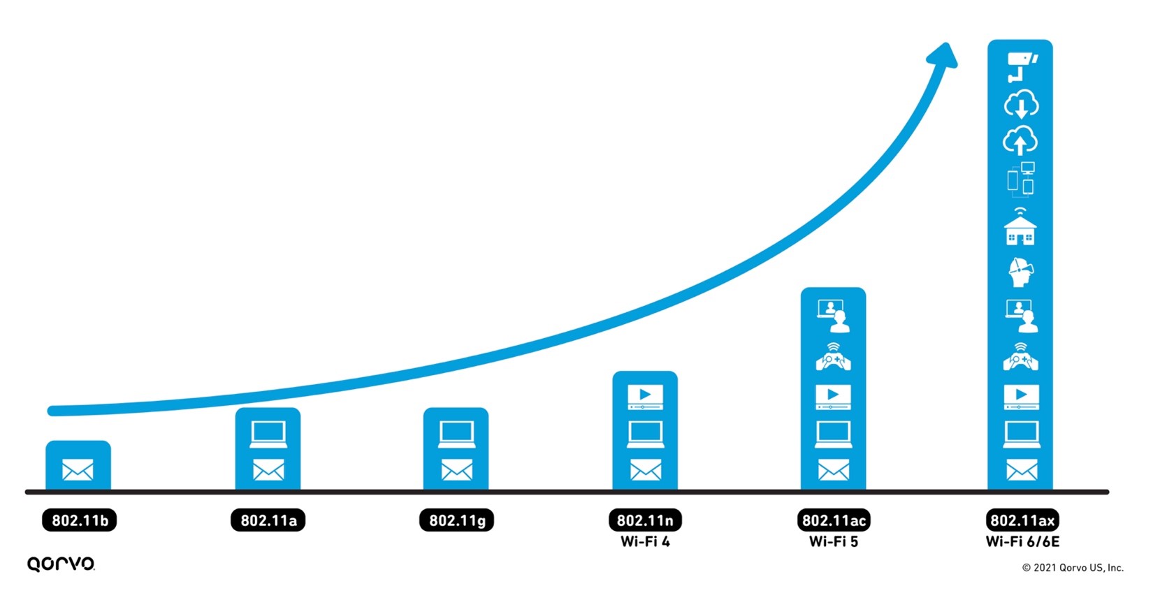
With this increase in usage comes an increase in expectations to access Wi-Fi anywhere — throughout the home, both inside and out, and at work. Meeting these expectations requires more wireless backhaul equipment to transport data between the internet and subnetworks. It also requires advancements in existing technology to reach the capacity, range, signal reliability and the rising number of new applications wireless service providers are seeing. Figure 1 shows the exponential increase in wireless applications — from email to videoconferencing, smart home capabilities, gaming and virtual reality — as wireless technology continues to advance.
Go In Depth:


Figure 1: The advancement of Wi-Fi

The 802.11 standard has now advanced onto Wi-Fi 6 and Wi-Fi 6E, providing service beyond 5 GHz and into the 6 GHz area up to 7125 GHz, as shown in Figure 2. This higher frequency range increases our video capacities for our security systems and streaming.
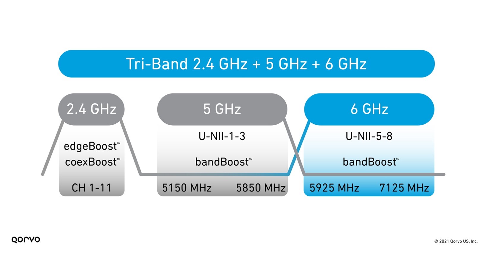

Figure 2: Tri-Band Wi-Fi frequency bands

However, working in higher frequency ranges can bring challenges such as more signal attenuation and thermal increases — especially when trying to meet the requirements of small form factors. To meet these challenges head-on, RF front-end (RFFE) engineers need to take existing technology to another level. One of those advancements has been in BAW filter technology now being used heavily in Wi-Fi system designs.

As shown in Figure 3 below, Qorvo has three BAW filter variants that boost overall Wi-Fi performance, maximize network capacity, increase RF range, and mitigate interference between the many different in-home radios operating simultaneously.
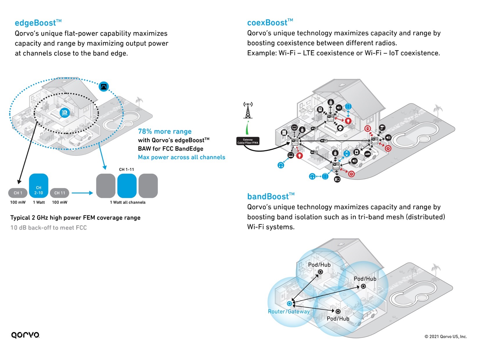

Figure 3: bandBoost, edgeBoost, and coexBoost filter technology performance

5 & 6 GHz bandBoost Filters

In a previous blog post called An Essential Part of The Wi-Fi Tri-Band System – 5.2 GHz RF Filters, we explored how using bandBoost filters like the Qorvo QPQ1903 and QPQ1904 can help reduce design complexity and help with coexistence. We also explored how these bandBoost filters provide high isolation, helping to reduce that function on the antenna design, allowing for less expensive antennas. Therefore, the RFFE isolation parameter no longer needs to rest entirely on the antenna. This reduces antenna and shielding costs – providing up to a 20 percent cost reduction.

These bandBoost BAW filters play a key role in separating the U-NII-2A band from the U-NII-2C band, which only has a bandgap of 120 MHz, as shown in Figure 4. Using these filters, we can attain Wi-Fi coverage reaching every corner of the home with the highest throughput and capacity. Using this solution in a Wi-Fi system design has shown increases in capacity for the end user up to 4-times.

Unlicensed National Information Infrastructure (U-NII)

The U-NII radio band, as defined by the United States Federal Communications Commission, is part of the radio frequency spectrum used by WLAN devices and by many wireless ISPs.

As of March 2021, U-NII consists of eight ranges. U-NII 1 through 4 are for 5 GHz WLAN (802.11a and newer), and 5 through 8 are for 6 GHz WLAN (802.11ax) use. U-NII 2 is further divided into three subsections: A, B and C.
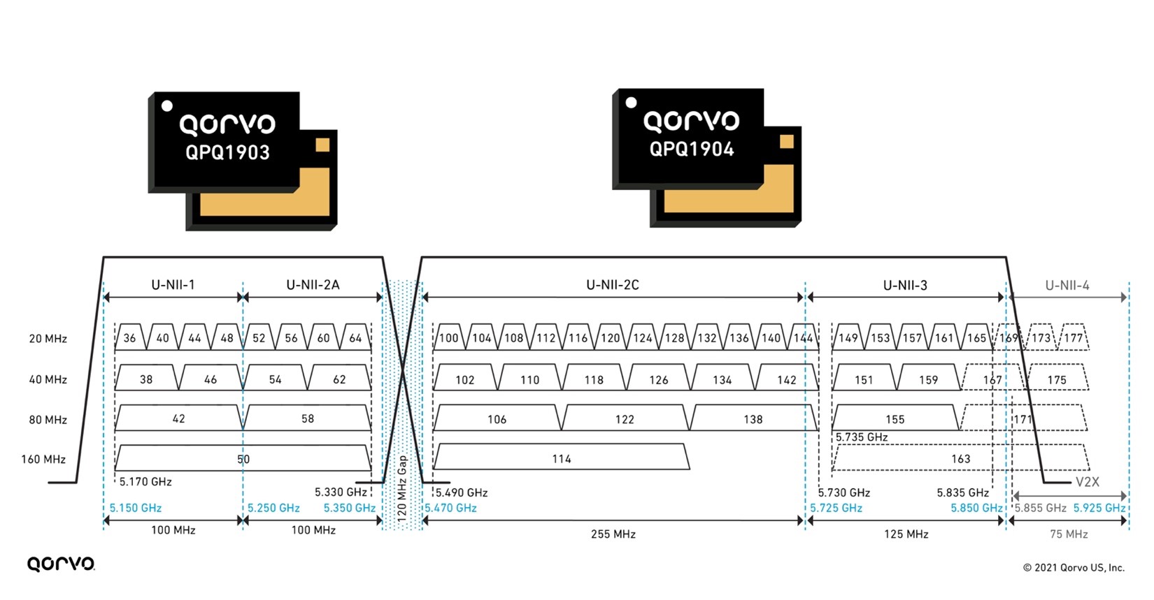

Figure 4: 5 GHz bandBoost filters and U-NII 1-4 bands

These filters are much smaller than legacy filters on the market used in Wi-Fi applications — allowing for more compact tri-band radios. They also have superior isolation achieving greater than 80 dBm system isolation for designers. This helps engineers meet the stringent Wi-Fi 6 and 6E requirements.
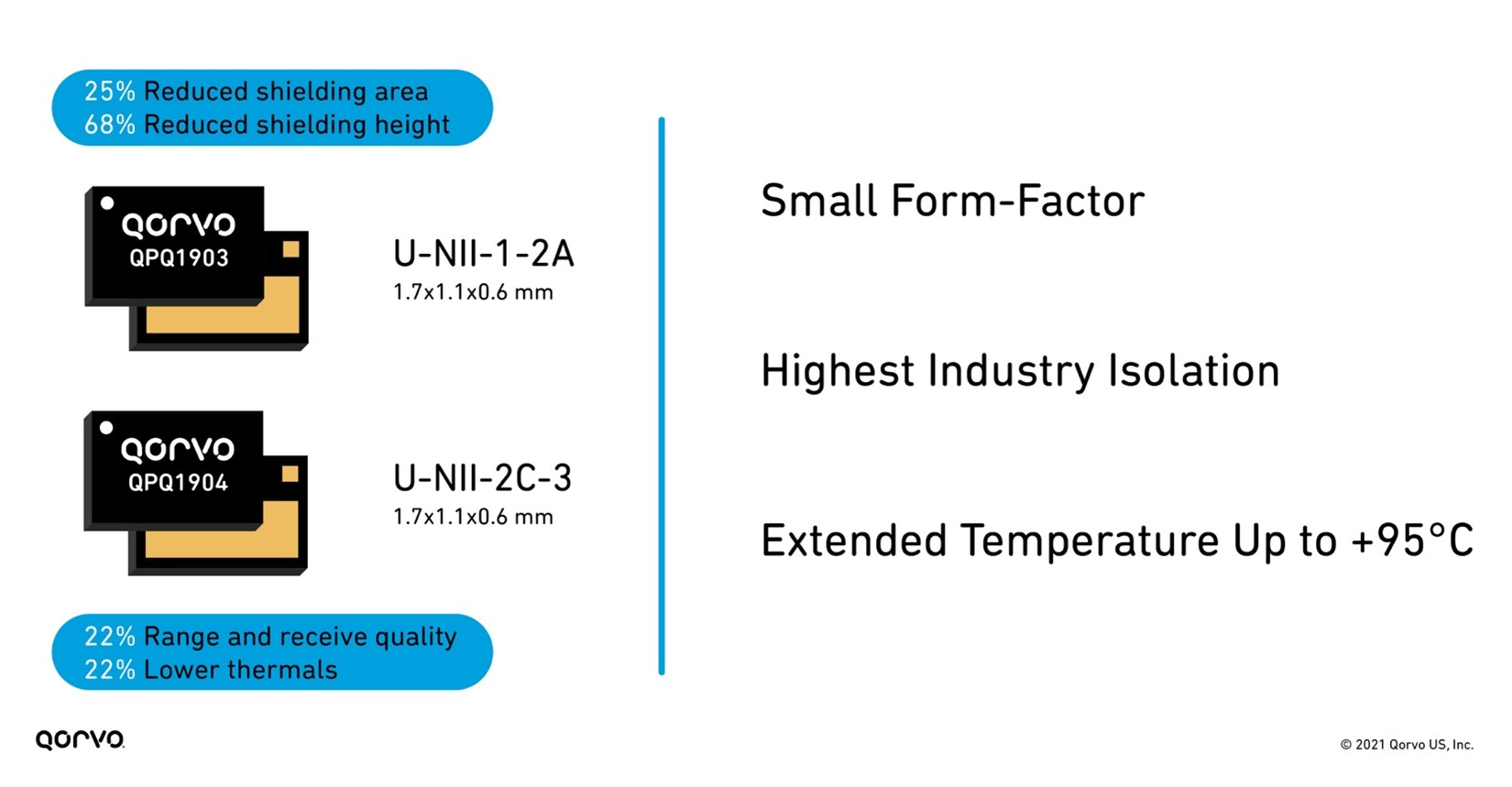

Figure 5: Benefits of using QPQ1903 and QPQ1904 bandBoost filters

The addition of multiple-input multiple-output (MIMO) and higher frequencies in the 6 GHz range increases system temperatures. With more thermal requirements, robust RFFE components are a must. Much of the industry specifies their parts in the 60°C to 80°C range, but higher temperature operation is needed based on the system temperatures produced in this frequency range. To solve these challenges, many hours of design effort have been spent on increasing the temperature capabilities of BAW. As product designs in Wi-Fi 5, 6/6E, and soon to come Wi-Fi 7, development has become more challenging, and as new opportunities like the automotive area opened for BAW, the push for higher temperature capability has come to the forefront.

Qorvo BAW technology engineers have delivered innovative devices by designing those that exceed the usual 85°C maximum temperature working range, going up to +95°C. The benefits this creates are great for both product designers and end-product customers. Now sleeker devices are achievable, as end-products no longer require large heat sinks. This also reduces design time as engineers can more easily attain system thermal requirements. One other advancement related to heat is that the bandBoost BAW products work at +95°C while still meeting a 0.5 to 1 dBm insertion loss.

This lower insertion loss improves Wi-Fi range and receive quality by up to 22 percent. Lower insertion loss also means improved thermal capability and performance as the RF signal seen at the RFFE Low Noise Amplifier (LNA) is improved. Below, Figure 6 shows the features and benefits of the QPQ1903 and QPQ1904 edgeBoost™ BAW filter.
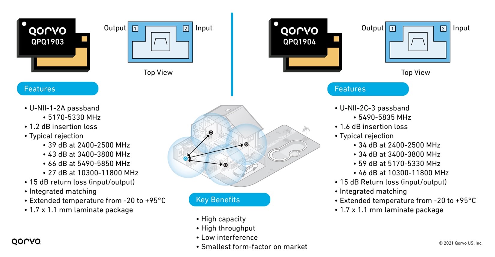

Figure 6: Features and benefits of QPQ1903 and QPQ1904

Not only are these filters providing benefits to the LNA, but they are small and perform well enough to install inside a tiny integrated Wi-Fi module package housing the LNA, switch, PA, and filter. Doing this drastically changes the end-product system layout making design easier and helps speed time-to-market. No longer are engineers burdened with matching and plugging individual passive and active components onto their PC board, but now they have all that done in these complex integrated modules called integrated front-end modules (iFEMs), creating a plug-and-play solution easily installed on their design.

A perfect example of this is the QPF7219 2.4 GHz iFEM, as seen in Figure 7. Qorvo has not only provided solutions with discrete edgeBoost BAW filters to increase output and capacity across all Wi-Fi channels. But Qorvo has gone a step further by including this filter inside an iFEM, our QPF7219, to provide customers with a drop-in pin-compatible replacement providing the same capacity and range performance outcome. This provides customers with design flexibility, board space in their design and is the first one of its kind on the market.
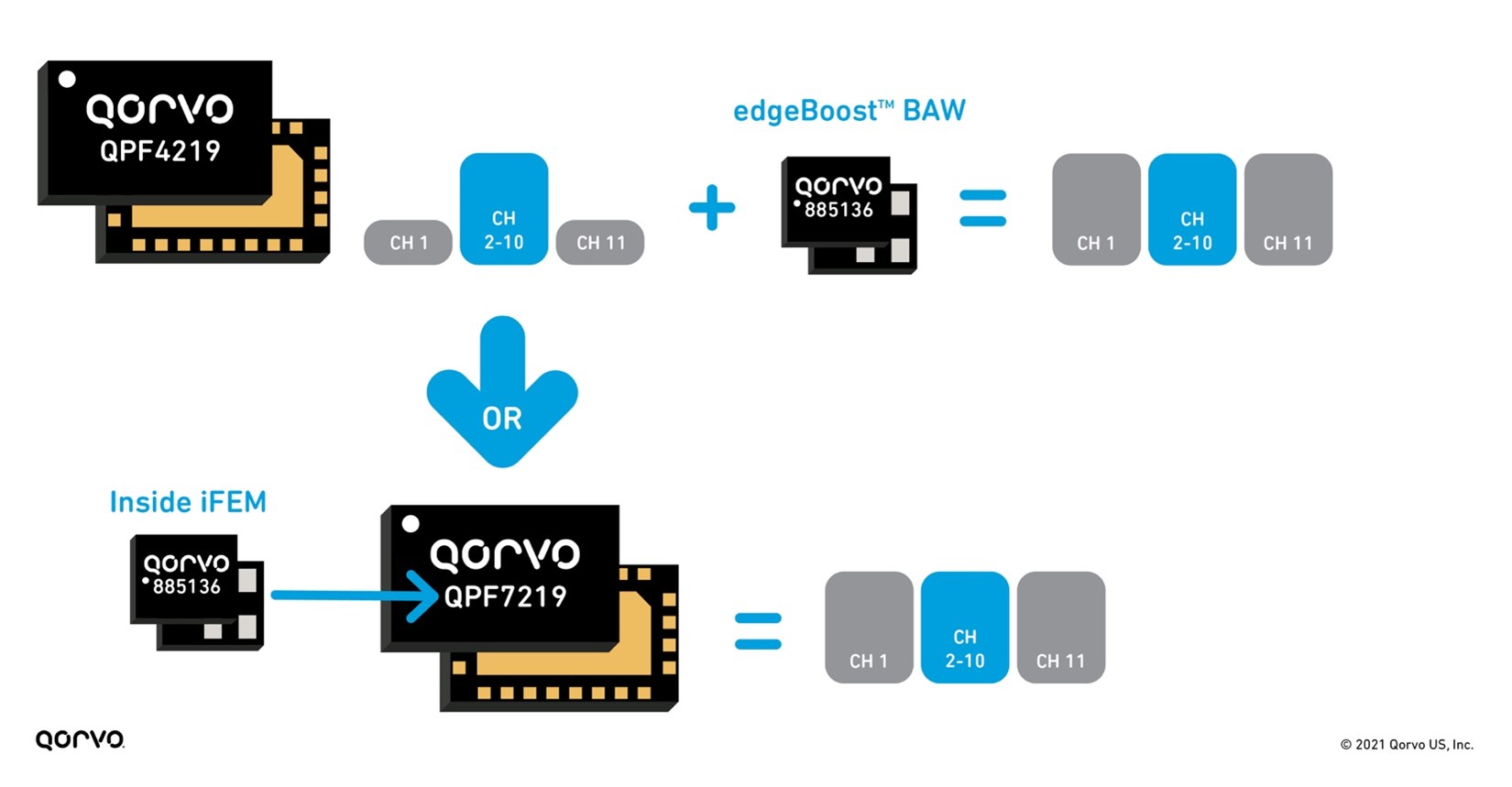

Figure 7: edgeBoost used as discrete and inside an iFEM

The need for smaller and sleeker product designs is always top of mind for Wi-Fi engineers. But to achieve the goal means component designers need to develop smaller products in many areas of the design, not just in one or two areas. From a tri-band Wi-Fi chip-set perspective, Qorvo has addressed this head-on. Qorvo has provided an entire group of iFEM alternatives to address the many signal transmit and receive lines in a product. This allows Wi-Fi design manufacturers to manage all the UNII and 2.4 GHz bands in a tri-band end-product design.
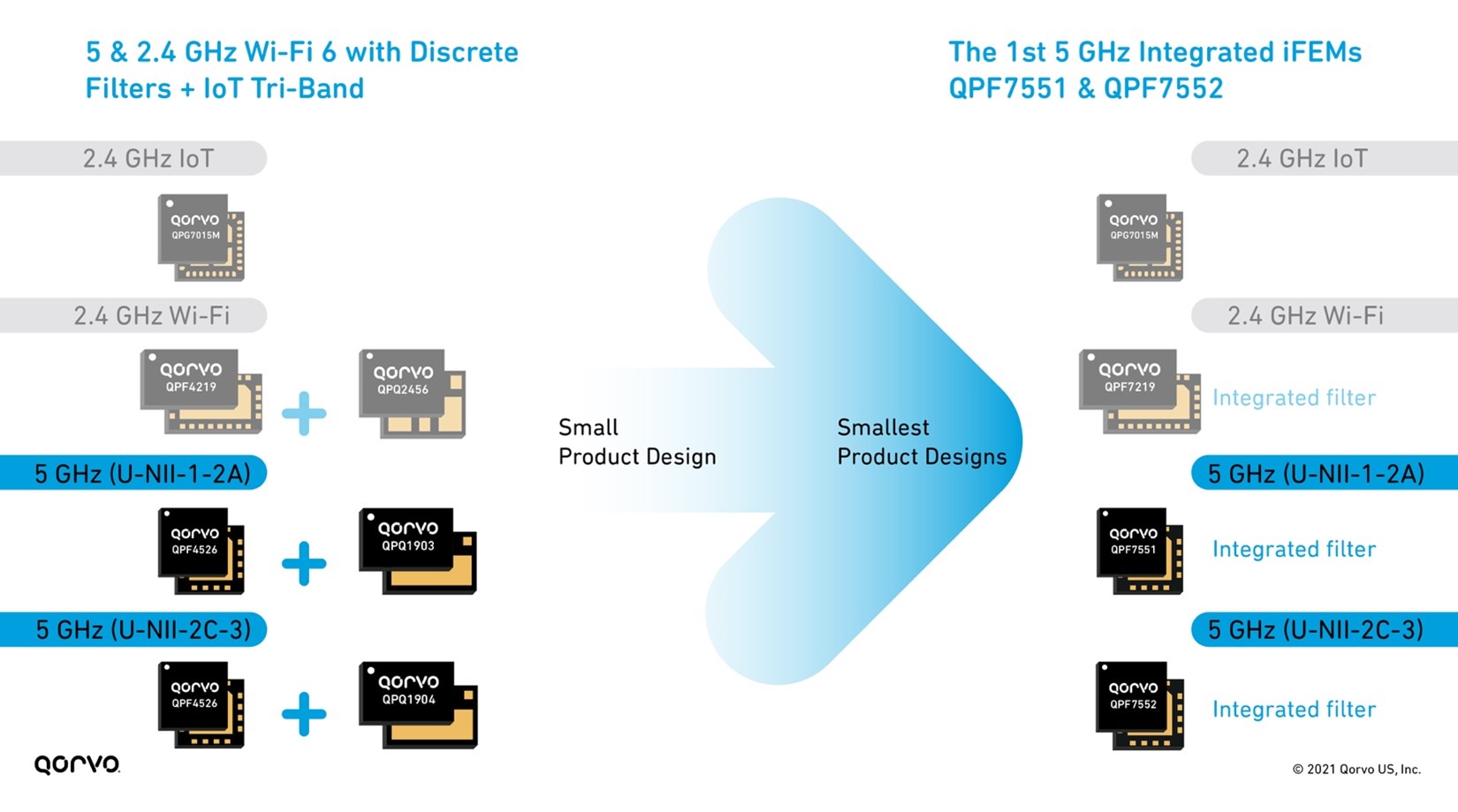

Figure 8: 2.4 & 5 GHz Wi-Fi 6 with IoT Tri-Band front-end solutions

This new design solution of combining the filter inside the iFEM equates to a smaller PC board and less shielding, as shown in Figure 9 below. Shielding matching and PC board space are expensive, not to mention the additional time associated with providing these materials. By placing all the RFFE materials inside a module, system designers can save cost, design faster, and get their products to market more quickly.
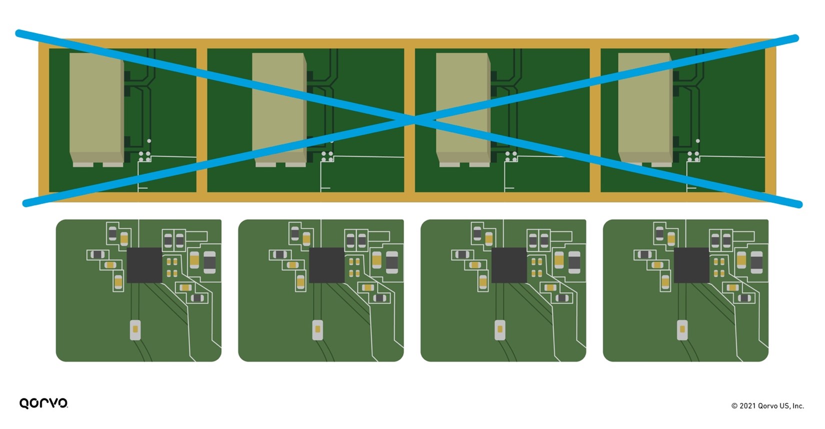

Figure 9: Putting the filter technology inside the iFEM removes shielding and reduces overall RFFE form-factor

As Wi-Fi system designers continue to be challenged with new specification requirements, they need newer or enhanced technologies to meet the need. By collaborating with our customers, we have provided state-of-the-art solutions to solve the tough thermal, performance, size, interference, capacity, throughput, and range difficulties seen by their end-customers. These solutions enable them to improve their designs to meet the Wi-Fi wave of today and in the future.


About the Author

Igor Lalicevic
Senior Marketing Manager, Wireless Connectivity Business Unit

With over 20 years of experience in the wireless industry, Igor helps Qorvo engineering teams create state-of-the-art RF components and solutions. He inspires the creation of new wireless connectivity products and eco-systems innovations that make a deep impact on our everyday life.

Why GaN is 5G’s Super ‘Power’

While some feel GaN is still a relatively new technology, many can’t dispute how it’s advanced to the head of the class. AKA, Gallium Nitride, GaN is a technology on the cusp of dethroning silicon LDMOS, which has been the material of choice in high power applications. GaN is a direct bandgap semiconductor technology belonging to the III-V group. It is increasingly being used in power electronics because of its higher efficiency, superior high-voltage sustainability, reduced power consumption, higher temperature attributes, and power-handling characteristics.

These attributes have thrust GaN into the 5G RF spotlight – especially when it comes to mmWave 5G networks. And, while we all have ‘heard’ the promises of 5G, today, many of us in big cities – about 5 million of us to be more precise – are starting to realize those promises as major wireless carriers roll 5G out to their customers. But we are not there yet. Not even close. The goal is to connect 2.8 billion users by 2025. To reach this goal means to revamp the entire mobile infrastructure – a complex undertaking. But it can be done. And with the help of GaN technology, 5G will be in billions of people’s hands before you know it.

Recently, Embedded.com invited Qorvo’s own Roger Hall to pen a series of 5G articles that explain the complexities of building out the infrastructure and where GaN fits into the innovations that will bring 5G to the masses. Here are summaries of each article with a link for a deeper dive.

5G and GaN: Understanding Sub-6 GHz Massive MIMO Infrastructure

In this article, Roger explains the advantages for carriers to implement Massive MIMO technology as a means to minimize cost and increase capacity when rolling out 5G. He explores sub-6 GHz and why it’s important for increasing the adoption and expansion of 5G. He also addresses how GaN is being used in Massive MIMO Infrastructure applications. Read more >

5G and GaN: The Shift from LDMOS to GaN

Here Roger examines how the power demands of sub-6 GHz 5G base stations are driving a shift from silicon LDMOS amplifiers to GaN-based solutions, and what makes GaN a viable technology for many RF applications. Roger also reviews some of the tradeoffs engineers need to consider between these two technologies and why GaN is becoming the clear winner in many 5G solutions. Read more >

5G and GaN: What Embedded Designers Need to Know

Building on the previous article, Roger provides insight for embedded designers to fully realize the potential of GaN. He discusses misconceptions about GaN, explores its characteristics, and offers best practices to maximize its performance. Read more >

5G and GaN: Future Innovations

In his fourth and final article in this series, Roger looks to the future of GaN’s role in base stations. He provides a peek into GaN innovations being made today that will improve linear efficiency, power density and reliability and the implications of those improvements. Read more >

For more information on GaN technology, visit here.

About the Author

About Roger Hall
Roger Hall

Roger is the General Manager of High-Performance Solutions at Qorvo. He leads program management and applications engineering for Wireless Infrastructure, Defense and Aerospace, and Power Management markets. This overarching role gives him a unique lens to view and interpret where RF technologies play fundamental parts in enabling future innovations.

Qorvo Blog Team

One part technical, one part content, and one part strategic, our small team is dedicated to connecting you with helpful, timely insights from some of the bright minds at Qorvo.

New capacitive sensing technology provides a more reliable and safer hands-on detection

The AS8579 sensor offers the simplest way for car makers to comply with the UN Regulation 79, while giving the best detection performance

For automotive design engineers, it is unusual to find a new technology solution which performs better than existing approaches, and which reduces cost, and which is easier to implement in the application. But that is exactly what a new capacitive sensing chip, ams’ new AS8579, offers when used for hands-on detection (HOD) in cars which provide driver assistance functions.
It is the result of the application of a familiar and proven measurement principle – I/Q demodulation – to the job of sensing the position of the driver’s hands on the steering wheel. And it is markedly superior to any of the existing technologies in use for HOD in cars. Watch the highlights in our video:


Essential safety requirement in new car designs

The HOD function is required by the United Nations Regulation 79, and applies to all new cars that have a Lane Keeping Assist System (LKAS) wherever ratified. It has already been adopted by the European Union for new production vehicles from 1 April 2021. The purpose of the HOD system is to continuously monitor the readiness of the driver to assume control of the steering system in an emergency, or in the event of the failure of the LKAS.

Various technologies have been developed to provide this HOD function, but have had limitations: it is possible for drivers who want to avoid holding the steering wheel to fool the current monitoring system, which could compromise safety. And some existing solutions also perform poorly in certain operating conditions.

One approach to HOD has been the torque sensor: this detects the continual, minute deflections produced when the driver grips the steering wheel. The big drawback of this technology is that it can be easily fooled: the driver may take their hands off the wheel and ‘hold’ it by pressing upwards against it with their leg.

The problems with torque sensors have led the car industry to adopt a form of capacitive sensing for HOD: it monitors the driver’s grip on the steering wheel by detecting the change in capacitance of the steering wheel when the driver’s hands – which absorb electrical charge – come into contact with it. This technique only requires a single sensor chip connected to a metal sensor element built into the steering wheel.

Until now, automotive system manufacturers have used the charge-discharge method of capacitive sensing: this is a well understood technique, as it has been applied for many years in products such as touchscreens and touch-sensing buttons. But detection fails when the driver wears gloves, and false detection signals generated by the presence of moisture or humidity undermine the safety performance of hands-on detection based on this method of capacitive sensing. This type of capacitive sensor can even be fooled if the driver wedges a capacitive object, such as a piece of fruit or a plastic water bottle, into the frame of the steering wheel. So again, the implementation of this charge-discharge method of capacitive sensing potentially compromises safety.

It is true that other technologies are already applied to other driver-monitoring functions. For instance, 2D optical sensing is in use in systems for monitoring the position of the driver’s head. However, these 2D optical-sensing systems are not capable of performing HOD. This means that capacitive sensing is the most viable technology for HOD that is ready for deployment today. And now ams has a new approach to capacitive sensing which will meet all the safety requirements imposed by the automotive industry, and which is simple to implement.

Better performance, lower cost

This new solution from ams provides better performance, and with fewer components than the existing charge-discharge technique for capacitive sensing.

By implementing reliable capacitive sensing based on I/Q demodulation, the AS8579 capacitive sensor performs HOD in a way which cannot be fooled. Like the charge-discharge method, I/Q demodulation is a proven and well-known technique for capacitive sensing. Its advantage is that it measures the resistive as well as the capacitive element of a system’s impedance. The effect of this is that, unlike the charge-discharge method, it works reliably in difficult conditions, such as in the presence of moisture, or when the driver is wearing gloves. And it cannot be fooled, so provides for assured detection of the driver’s grip on the steering wheel. And the added benefit of the AS8579-based solution is that it can operate via a heated steering wheel’s heater element, so it does not require a separate sensor element to be built into the steering wheel.

This is how the AS8579 eliminates the normal trade-offs in engineering design:

  • It performs better – it cannot be fooled, and it operates in all conditions
  • It costs less – it is a single-chip solution, and requires no dedicated sensing element in a heated steering wheel
  • It is easy to implement – the chip’s output is an impedance measurement, and the system controller simply applies a threshold value to determine whether hands are on the steering wheel or not.

Ready for use in automotive designs

The AS8579 is fully automotive qualified, and offers multiple on-chip diagnostic functions, ensuring support for the ISO 26262 functional safety standard up to ASIL Grade B. Operating at one of four selectable driver-output frequencies – 45.45kHz, 71.43kHz, 100kHz or 125kHz – the AS8579 offers high immunity to electromagnetic interference.

Automotive designers can start developing with the AS8579 automotive capacitive sensor immediately using its dedicated evaluation kit, the AS8579-TS_EK_DB. 

For more technical information or for sample requests, please go to capacitive sensor AS8579.


1D ToF family for mobile and industry brings the right combination of performance, size, and cost

Original blog post: https://ams.com/sensor-blog/1d-tof-family

ams 1D time-of-flight ranging sensor family offers mobile and industrial customers the right combination of performance, size, and cost to meet their needs.

When innovating sensor technology for a better lifestyle, ams engineers are balancing three attributes that are vital to customers: sensor performance, sensor size, and system cost. These variables are almost infinitely adjustable according to our customers’ evolving needs and specifications, competitive conditions, regulatory constraints or bill of materials requirements. How we design our product portfolio is based on our reading of the market and what our customers and close design partners tell us they want.

Customers are in a never-ending race to deliver better products and experiences. And as part of this, 1D Time-of-Flight sensors for front and world-facing applications are becoming increasingly important in the mobile, consumer, wearables, PC and industrial segments. The ams family of 1D ToF ranging sensors, developed for Laser Distance Auto-Focus (LDAF) applications within the mobile phone industry area also bringing benefit and increasingly winning in applications including PC user detection enabling auto lock/unlock, obstacle avoidance in robotic vacuum cleaners, inventory management, to name a few.

Broadening the family of time-of-flight (ToF) ranging sensors

ams has a strong history in bringing 1D ToF sensing innovations to market. Our most recent innovations include the world’s smallest 1D ToF sensor for accurate proximity sensing and distance measurement in smartphones’ – the TMF8701 and the TMF8801 which extends the operating range of the direct time of flight module to enable smartphones with space-saving accurate distance measurement. Now, ams brings rounds out the TMF sensor family with the TMF8805 adjusting the performance/cost variables to give customers greater flexibility and choice, especially for applications and products with massive growth potential or competing in the uncertainty of emerging markets.

TMF8805 – for mobile phone camera applications and more

The TMF8805 is a highly-integrated module which includes a class 1 eye-safe 940nm Vertical Cavity Surface Emitting Laser (VCSEL), Single Photon Avalanche Diode (SPAD) array, time-to-digital converter (TDC) along with a low power, high performance microcontroller. This system-in-module integration enables robust and precise distance measurements in the 20mm and 2500mm range, all packaged in the industry’s smallest footprint measuring only 2.2mm x 3.6mm x 1.0mm.

This high precision distance measurement is ideal for use in world-facing, LDAF mobile phone applications by enabling a fast, high-precision auto-focus feature. The new sensor joins the existing TMF8801 and TMF8701 time-of-flight sensors from ams, providing products which meet a range of cost and performance requirements across the mobile, wearable and consumer electronics, computing and industrial markets.

To meet evolving expectations in a transforming world, customers come to ams for our simple-to-integrate, plug-and-play sophisticated sensor systems, while often benefiting from the ‘speed premium’ of our supplier ecosystem and specialist expertise. The TMF8805 time-of-flight sensor is now in mass production and an evaluation kit featuring the TMF8805 along with a comprehensive evaluation GUI is also available.